07-23-2021
Editor’s Note: This content is republished from the MicroZed Chronicles, with permission from the author.
If I’m being honest, my university classes on control engineering were not my favorite. However, working as an engineer – and especially in embedded systems -- you come across applications that often call for the use of control theory.
One very commonly used algorithm is the Proportional Integral Derivative Controller or PID Controller. PID Controllers are used to control temperatures, pressures, motor positions, and flow rates of a wide variety of applications. One place I regularly see it is in high-end image processing systems that use thermal electric coolers or other cooling systems to cool down image sensors. This reduces the noise in the image. For scientific imaging, lower noise enables a better image with the potential for more discoveries.
The PID Controller algorithm is not too tricky to implement since it only requires addition, multiplication, division and subtraction. However, determining the three coefficients used to ensure that the PID loop is stable can require a little additional time once the algorithm has been implemented.
The PID uses three terms at its most basic level.
Proportional - This measures the difference between the desired value and the measured value. The proportional value is a measure of the current position. There will always be an error due to how it works.
Integral - This integrates the error over time. The integral term is the historic cumulative value of the error. As the error is eliminated, the integral term stops growing.
Derivative - Calculates the rate of change and is predicting the future trend of the error.
Each term also has an associated gain, KI, KP or KD to help us tune the behavior of the PID Controller algorithm. The D term is not always used in the implementation and it is also not unusual to implement PI controllers.
PID often uses floating point maths to implement. As such, we can implement them in RTL using libraires such as the VHDL Fixed/Float libraires. Alternatively, we can implement the PID using high-level synthesis which is what we will use for this example today. This gives us the ability to use either floating point or arbitrary precision fixed point mathematics. It also provides me the ability to quickly and easily change the interfacing on the block by the addition or not of pragmas.
This is important because normally when I implement these types of controllers, they are targeted for pure FPGA implementations (which may or may not contain a soft-core processor) or a smaller Zynq-7000 SoC part (7007, 7010, 7020 etc.). As such, I may want a more traditional vector interface than a AXI interface if there is no processor in the design.
We can use a type definition in a header file to enable flexibility in the HLS algorithm between floating point and arbitrary fixed point without the need to make multiple changes. For this example, I am going to implement it as a floating-point solution, mainly because I have never demonstrated how to write the floating-point values into the AXI registers.
The actual source code for the PID is pretty straight forward and can be seen here.
I have declared the previous error and previous integral as global static variables to ensure they retain their values between iterations.
Algorithm wise, the user can load in KP, KI, KID, Ts and Pmax on the fly as the application is running. We could easily make additions to store the integral value or restart the controller using additional registers. This would enable the PID implementation to be time sliced and used for more than one implementation.
To test and configure the PID, the test bench applies a range of input temperatures that are both well above the intended target set point and also to ensure the set point is achieved. The PID in this example has been designed to deliver a power (in watts) to maintain the temperature of an optical bed. In this case, we need to heat it up not down. I’m sure you can guess that it is space application.
This PID was simulated in Vitis HLS for both C Simulation and Co-Simulation with the results exactly as expected.
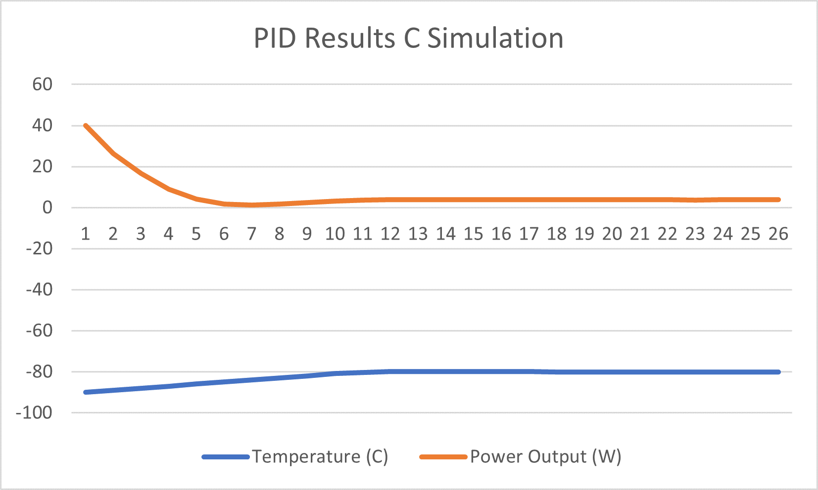
With the algorithm behaving as I expected, the next step to synthesize and export the IP for inclusion into a Vivado project. This time we will target the Cora Z7S board.

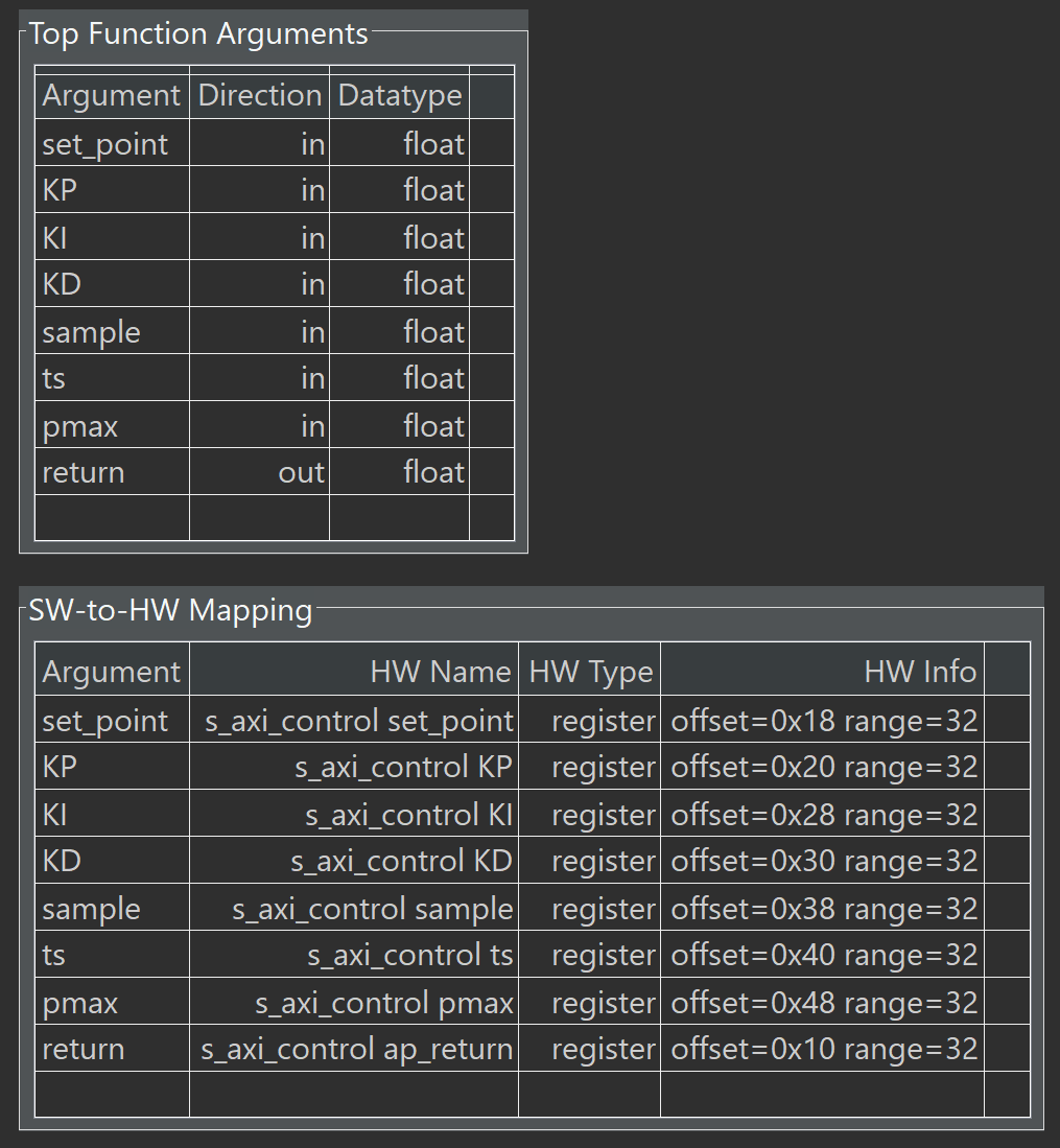
The completed block diagram below reflects interfaces that are synthesized into a AXI interface.
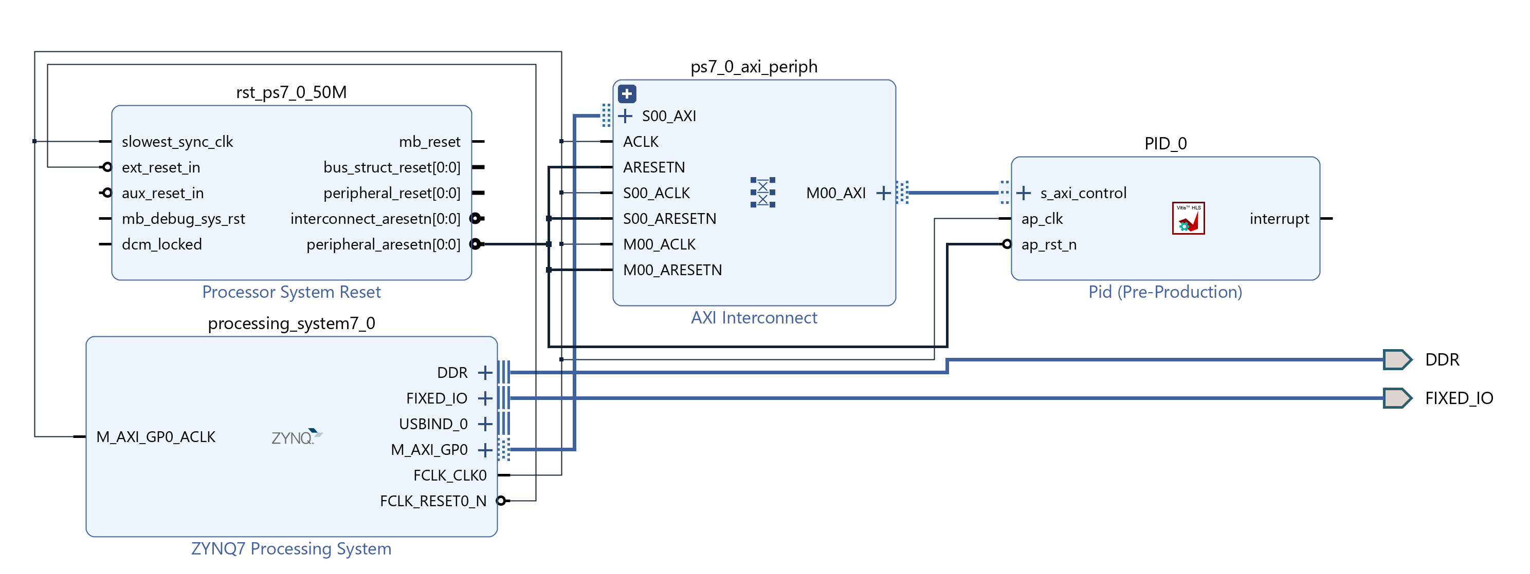
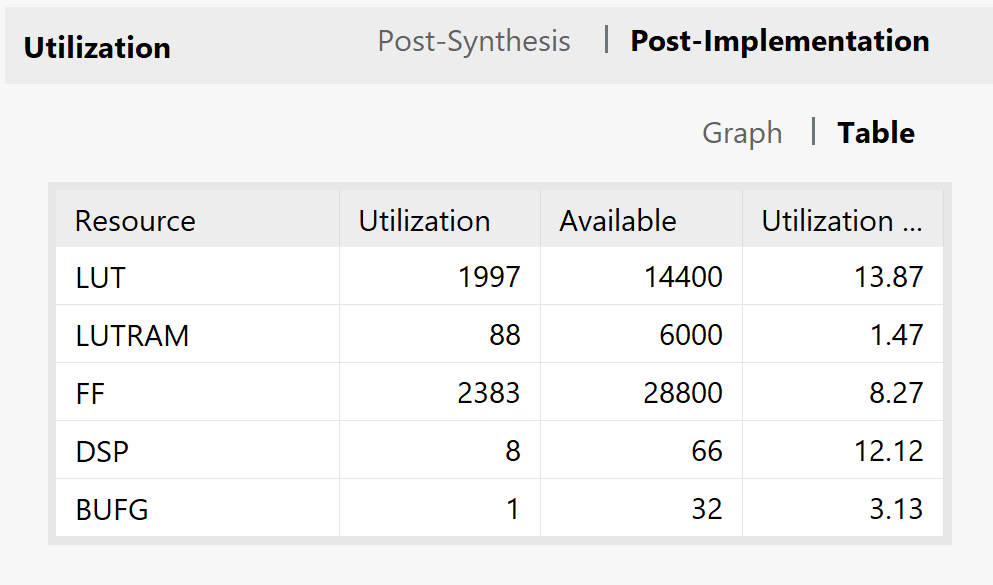

It’s nice that the project can be built simply and then exported to Vitis. In Vitis, we can reuse several elements of the HLS test bench in the development of the application which drives the IP core.
Since we are using a AXI interface, Vitis HLS very kindly provides us a driver that can be used in Vitis to drive the IP core. However, when you use floating point inputs into the IP core, the driver expects them as a U32. If we do a conversion from Float to U32, we will lose significant accuracy. Therefore, the way to approach this is to use pointers and casting.
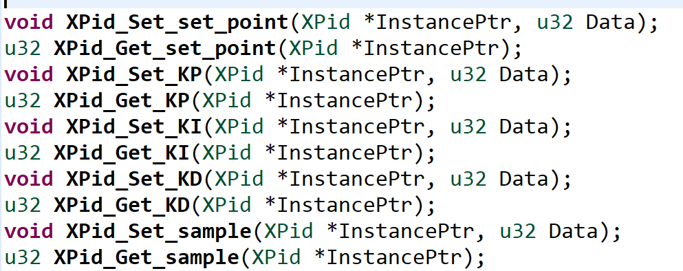
In essence, we declare the variable as a float and then, in the function, call set a U32 pointer to the address of the float variable and use the indirection operator to read the value.
XPid_Set_set_point(&pid, *((u32*)&set_point ));
Running the application, gives the following results.
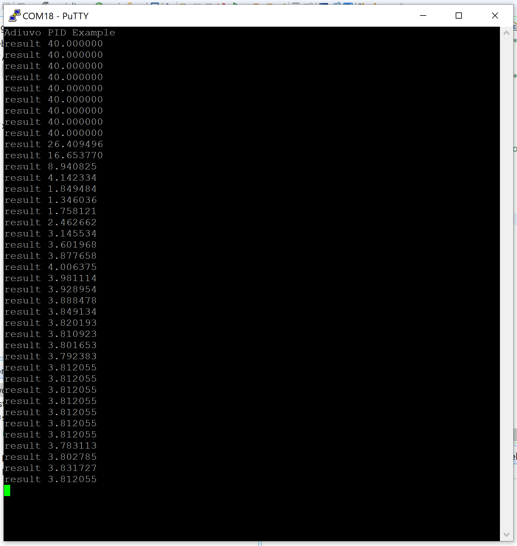
The implementation in hardware works identically to the software version as would be expected.
Of course, for different applications, you would need to determine the KP, KI, and KD variables which can be used for your application but there is a lot of information on training PID out there.
The real beauty of this is that because it was implemented in C, you can using HLS if you want to run the algorithm from a processor core in place of being in the logic.