09-17-2021
Editor’s Note: This content is republished from the MicroZed Chronicles, with permission from the author.
On my explorations with the Kria board so far, all the imaging has been using a web camera over USB. Of course, we also can capture images using the MIPI interfaces on the Kria by using the two ISP interfaces or the RPI interface.
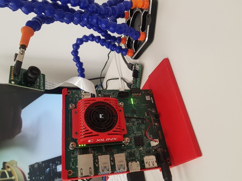
I have several Digilent Pcam 5C cameras floating around the office so I thought it would be a good idea to get the RPI camera port working with the Kria. This interface uses two MIPI lanes along with the associated clock. The imager is also configured using a I2C interface.
We have created MIPI image processing solutions several times before on the Ultra96-V2, Genesys ZU, Zynqberry Zero, and most recently the Seeed Spartan Edge Accelerator Board.
The first thing to do when creating a solution like this is to understand the hardware design and paths taken by the MIPI and the I2C interface. The MIPI interface is straightforward and routed directly to the FPGA pins, while the I2C interface is routed via a switch.
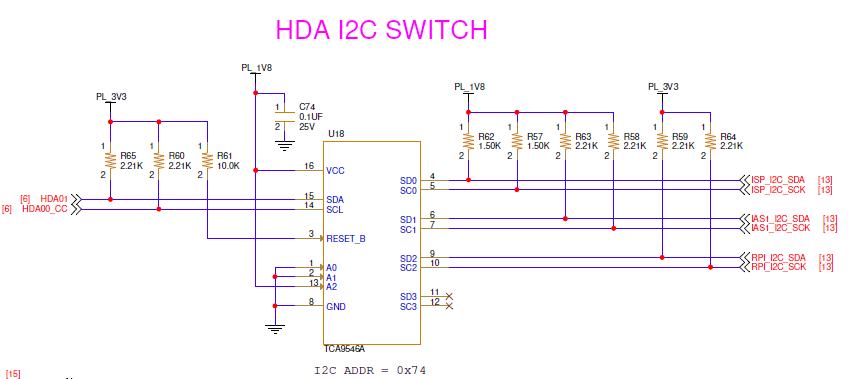
In order to be able to configure the camera, we first need to set the switch to the correct channel.
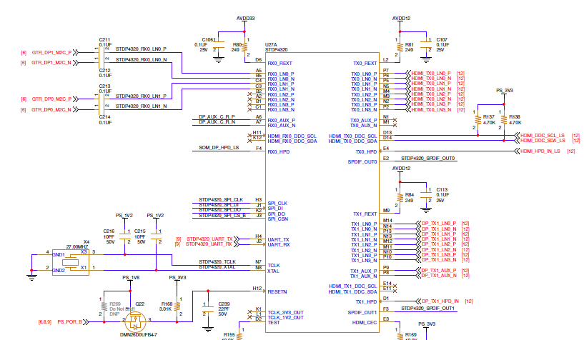
In addition, we also need to be able to control the output path. We will be using the DisplayPort output for this example. One of the nice things about the Kria is that the DisplayPort output from the MPSoC device is connected to a splitter. This receives the DisplayPort and splits it to provide both DisplayPort and HDMI outputs. As a result, we don’t need to do any configuration of this splitter. We only need to provide the DisplayPort input.
The Vivado design uses the MIPI CSI-2 receiver subsystem, as the output from the subsystem is raw video a simple ISP is created in the programmable logic to do DeMoasic (RGB conversion) and then Gamma correction. The output of the video is then stored in the Kria PS DDR4 memory using VDMA.

Since this is a bare metal application, the VDMA output is converted from an AXI stream to video and applied to the live video input on the MPSoC.
To start this design, I configured a new project for the Kria that enables the automatic configuration of the PS correctly for the SOM.
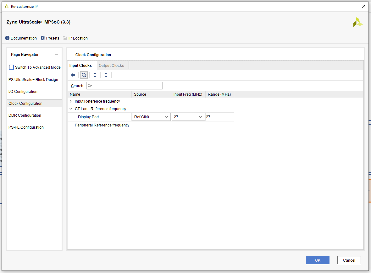
To use the DisplayPort, however, we need to make some configuration changes to the MPSoC. The first thing we need to do is enable the DisplayPort. We are using the Dual Lower GT lanes and MIO 27..30 for the Aux channels.

We also need to provide the correct reference clock for the DisplayPort. For this, we use the Ref Clock 0 with the input frequency being 27 MHz.
Once this is completed, we can build the design and generate the bit stream. The Vitis application is the same as the one I have used for previous developments using MIPI. The only difference is that the I2C switch is accounted for before I detect and configure the camera.
Running the application on my Kria card resulted in the Pcam 5C camera image being output on a HDMI display.
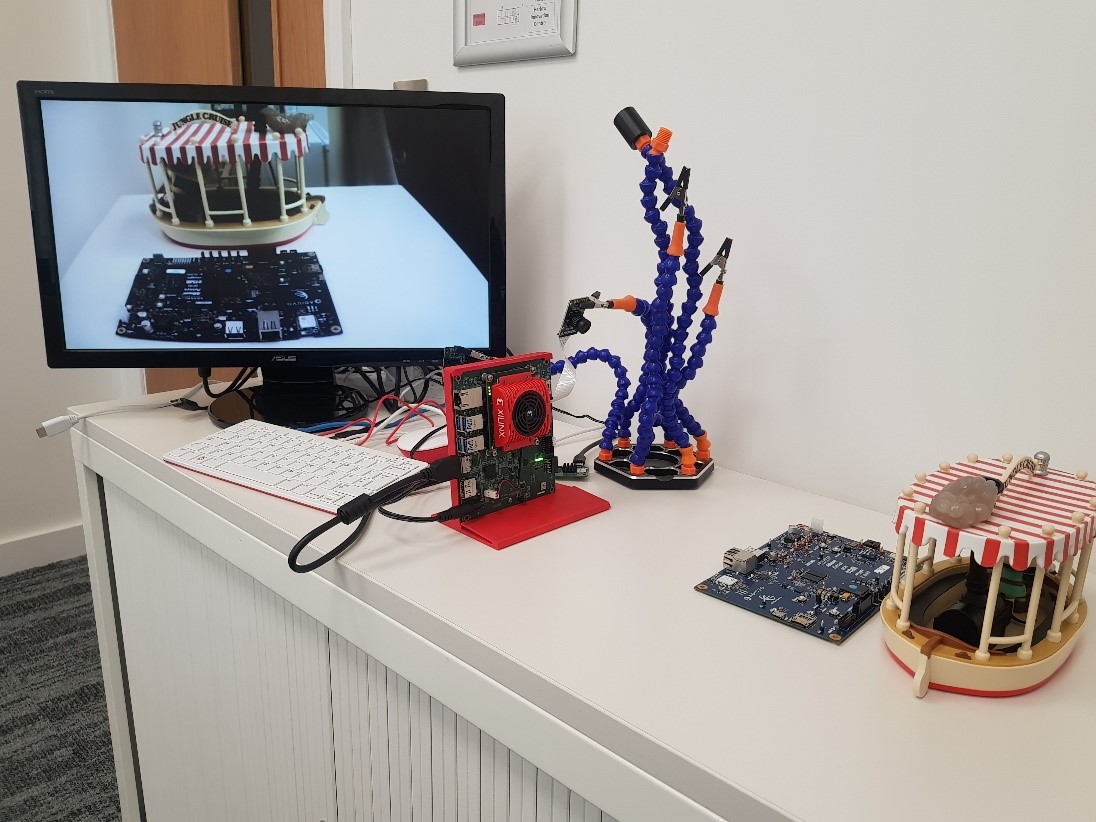
The software and hardware design can be found here.
The next step is to use the same camera to recreate the same applications that come with Kria out of the box. Stay tuned!