AR# 40398
|Virtex-6 FPGA ML605 Evaluation Kit - Board Debug Checklist
描述
The ML605 Evaluation Board Checklist is useful to debug board-related issues and to determine if a Boards RMA is the next step.
解决方案

1. Switch / Jumper Settings
2. LEDs
3. JTAG Initialization
4. JTAG Configuration
5. Slave SelectMAP Configuration
6. Master BPI Configuration
7. System ACE Configuration
8. System Monitor
9. IBERT
10. PCIE-Gen2
11. Multiboot
12. DDR3
1. Switch / Jumper Settings
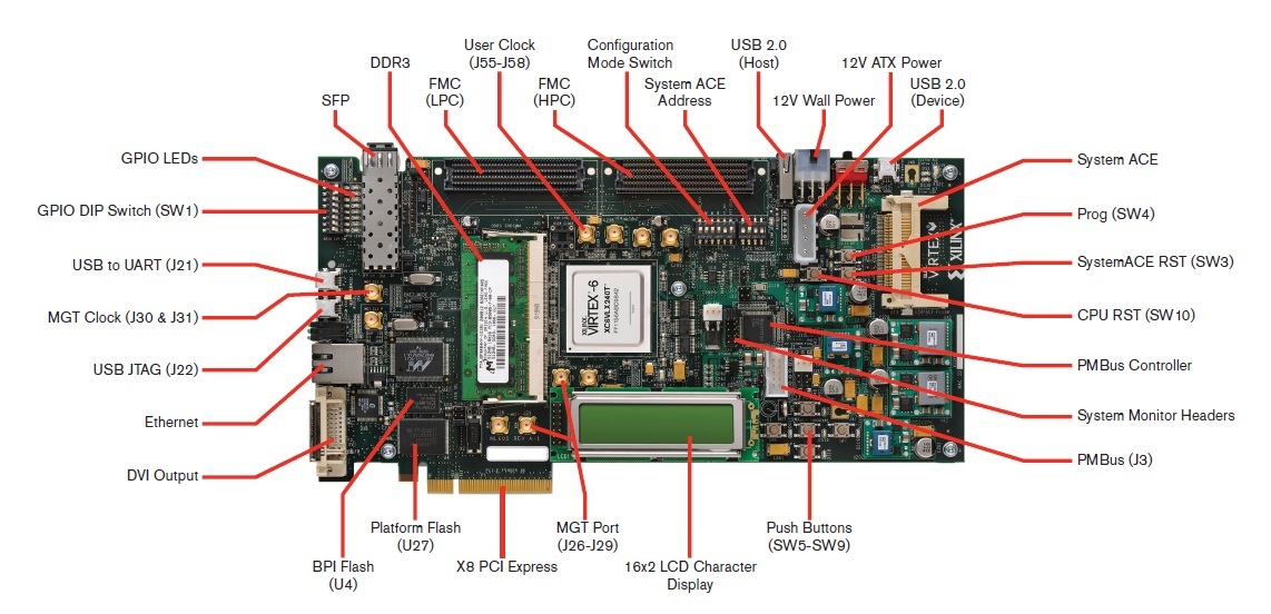
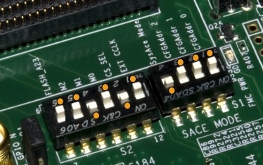
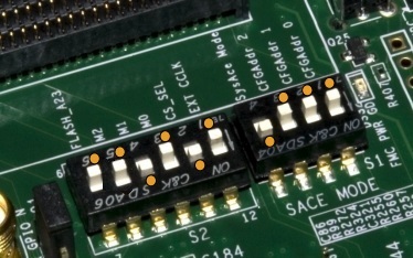
Default Switch and Jumper Settings for the ML605 are:
Start from a known, safe scenario by verifying the default Switch and Jumper settings. You can then set switches / jumpers for your application.
a. GMII
- J66 1-2
- J67 1-2
- J68 no jumper
b. FMC Bypass
- J18 1-2 (bypass FMC LPC connector)
- J17 1-2 (bypass FMC HPC connector)
- J69 1-2 (near Compact Flash connector)
c. System Monitor
- J19 1-2 (Test_mon_vrefp sourced by U23, REF3012)
- J35 9-11 (measure voltage on R-kelvin on 12V rail)
- J35 10-12 (measure voltage on R-kelvin on 12V rail)
d. SFP
- J54 1-2 (Full BW)
- J65 1-2 (SFP Enable)
e. PCIe Lane Size Select
- J42 1-2 (nearest PCIe fingers)
f. System Ace Error Disable Jumper
Power on Test LEDs Status (below) are indications of Board health.
- Check that the FAN spins.
- Check the status of the following LEDs at Power ON, if not, try reset the TI power controllers using the XML script. See (Xilinx Answer 39037):
- DS25 - 12V PWR - ON
- DS30 - SYSACE CF error LED (blinks red with No CF card)
- DS32 - FMC PWR Good - ON
- DS28 - MGT AVTT - ON
- DS27 - MGT AVCC (under LCD) - ON
- DS29 - DDR3 PWR Good (under LCD) - ON
- Check 6 Ethernet LEDs near RJ45 Ethernet jack P2. Cycle Power ON and OFF and see that all LEDs blink.
- Check 12V Power LED is Green; if not, follow these steps:

- Check the JTAG chain is initialized properly. If not, follow these steps:

- Verify switch S2 settings:
- S2.1 = OFF
- S2.2 = ON
- S2.3 = ON
- S2.4 = OFF
- S2.5 = ON
- S2.6 = OFF
For JTAG configuration mode
- Verify FMC bypass jumper positions J17 and J18.
Pin 1 and 2 to be connected by jumper in case FMC card is not present.
If using an FMC card, still try with jumpers on pin 1 and 2 of J17 and J18. If this works, then there might be an issue with the FMC connector. - Verify use of a supported OS.
- Run ML605 Built-In Self Test Application Test 2 to check for errors (see XTP056 for more details).
If JTAG chain not initialized in iMPACT:
- Check cable drivers are loaded on host PC.
- Check system properties and environment variables.
- USB port enabled?
- iMPACT tools correctly installed?
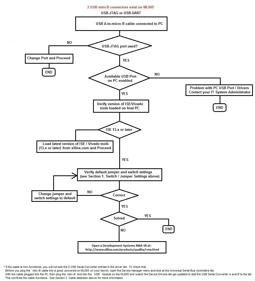
- There are 2 USB mini-B connectors on the board; USB-JTAG and USB-UART. Verify USB-JTAG is used to initialize the chain.
- Check step 2e. above.
JTAG chain initializes, but JTAG configuration fails:
- Check 12V Power LED is Green; if not, see step 2d. above.
- Verify S2 settings; see step 2f. above.
- Check step 2g. above.
- Check step 2h. above.
Problems during Slave SelectMAP configuration:
- Check 12V Power LED is Green; if not, see step 2d. above.
- Verify S2 settings:
S2.1 = ON
S2.2 = OFF
S2.3 = OFF
S2.4 = ON
S2.5 = ON
S2.6 = Don't Care - Ensure configuration from the System ACE card is disabled by setting switch S1.4 = OFF.
- Restore Flash contents using factory supplied default image. See XTP055 for instructions.
Problems during Master BPI configuration:
- Check 12V Power LED is Green; if not, see step 2d. above.
- Verify S2 settings:
S2.1 = OFF
S2.2 = ON
S2.3 = OFF
S2.4 = ON
S2.5 = OFF
S2.6 = OFF - Ensure configuration from the System ACE card is disabled by setting switch S1.4 = OFF.
- Restore Flash contents using factory supplied default image. See XTP055 for instructions.
Problems during System ACE configuration:
- Check 12V Power LED is Green; if not, see step 2d. above.
- Verify S1 settings: S1.4 = ON.
- Verify CF image address is set correctly using S1.1, S1.2, and S1.3.
- Verify CF card is inserted properly in its socket.
- Format and restore Compact Flash card with factory supplied default image; see rdf0022.zip. See (Xilinx Answer 14456) for formatting instructions.
- Run ML605 Built-In Self Test Application to check for errors; see XTP056 for more details.
Configuration is OK, System Monitor port not working:
- Verify J19 and J35 jumper position; check (UG534) for details.
- Use 12.2 or later version of ISE software.
- Download and run rdf0012.zip and XTP048 (whichever version is appropriate for silicon and software version) from the ML605 Reference Designs page.
- Read the ML605 System Monitor Reference Design document; see XTP048.
- Run ML605 Built-In Self Test Application Test 9 to check for errors; see XTP056 for more details.
Configuration is OK, IBERT not working:
- Verify S2 switch is set to 0101XX.
- Verify S1 switch set to 0XXX.
- Check SMA loop back cable used correctly (if using MGT loopback). When using an SMA cable, connect J28 to J26 and J29 to J27.
- Download and run rdf0066.zip and XTP091(whichever version is appropriate for silicon and software version, i.e., xtp091_13.2_c.pdf and rdf0066_13.2_c.zip for 13.2 ISE and Production Silicon) from the ML605 Reference Designs page.
- Read and follow the guidelines in XTP091.
- ML605 - IBERT Known Issues: (Xilinx Answer 33604) and (Xilinx Answer 34683).
Configuration is OK, PCIE-Gen2 interface not working:
- Verify S2 switch is set to 011001.
- Verify S1 switch is set to 0XXX.
- Ensure PC power connected to J25 and Power switch turned off. Do not use PCI connector PC power supply. Do not use both ML605 Power brick connector (J60) AND 4-pin ATX connector at the same time.
- Ensure PCIE core was created correctly (refer to UG517).
- Download and run rdf0009.zip and XTP045 (whichever version is appropriate for silicon and software version, i.e., xtp045_13.2_c.pdf and rdf0009_13.2_c.zip for 13.2 software and Production Silicon).
- Read and follow the guidelines in XTP045.
- ML605 - PCIE Known Issues: (Xilinx Answer 35675) and (Xilinx Answer 40279).
Configuration is OK, Multiboot not working:
- Verify S2 switch is set to 001010.
- Verify S1 switch is set to 0XXX.
- Verify steps taken to program ML605 with Multiboot bitstream in iMPACT. (refer to UG360).
- Download and run rdf0007.zip and XTP043 (whichever version is appropriate for silicon and software version, i.e., xtp043_13.2_c.pdf and rdf0007_13.2_c.zip for 13.2 software and Production Silicon).
- Read and follow the guidelines in XTP043.
Configuration is OK, MIG / DDR3 interface not working:
- Ensure DDR3 DIMM module inserted correctly.
- Verify S2 switch is set to 001010 (Position 6 > Position 1).

- Verify S1 switch is set to 0XXX.
- Ensure correct steps are followed in the CORE Generator tool to generate required MIG IP core and modified UCF file carefully as per MIG IP. Ensure this runs properly (refer to UG406).
- Download and run rdf0011.zip and XTP047 (whichever version is appropriate for silicon and software version; i.e., xtp047_13.2_c.pdf and rdf0011_13.2_c.zip for 13.2 software and Production Silicon).
- Read and follow the guidelines in XTP047.
链接问答记录
主要问答记录
| Answer Number | 问答标题 | 问题版本 | 已解决问题的版本 |
|---|---|---|---|
| 43748 | Xilinx Boards and Kits - Debug Assistant | N/A | N/A |
子答复记录
| Answer Number | 问答标题 | 问题版本 | 已解决问题的版本 |
|---|---|---|---|
| 54022 | How can I order TI USB Interface Adapter EVM from Texas Instruments? | N/A | N/A |
相关答复记录
| Answer Number | 问答标题 | 问题版本 | 已解决问题的版本 |
|---|---|---|---|
| 40399 | Spartan-6 FPGA SP605 Evaluation Kit - Board Debug Checklist | N/A | N/A |
| AR# 40398 | |
|---|---|
| 日期 | 11/23/2016 |
| 状态 | Active |
| Type | 综合文章 |
| Boards & Kits | |