MicroZed Chronicles: Porting Bluespec RISC-V to Another Board
October 15, 2021
This content is republished from the MicroZed Chronicles, with permission from the author.
A few weeks ago, we looked at the new Bluespec RISC-V core which is deployed on an Arty A7-100T. I was curious to see how easy it would be to port the RISC-V core to another FPGA because the true value of the RISC-V core is its portability.
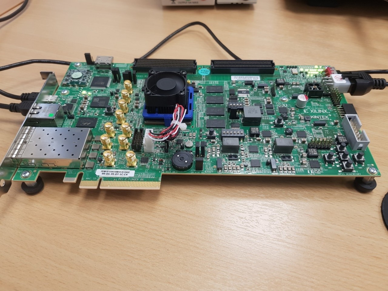
In this blog, I am going to demonstrate how we can port the Bluespec RISC-V core to the KCU105 Evaluation Board which contains a Kintex UltraScale FPGA. This is an interesting port from the Arty A7-100T because the Kintex UltraScale FPGA is much larger and higher performing and could possibly have several RISC-V processors deployed inside it in a real application. Here are the key differences between the two boards:
- Clock is 125 MHz compared to 100 MHz
- Clock input is differential compared to single ended
- Pin Out of the UART, Clock and Reset
- Different USB UART devices
- Different Reset Active Levels – Active High vs Active Low
As you can see, the differences include not only the interfaces and clocking of the target FPGA, but also the configuration on the board itself. Having different interfacing devices is important because it enables me to demonstrate how to handle any issues that crop up in the scripts.
Porting the design is pretty straight forward. We will be following a script-based approach just as we did in the original example.
The out-porting journey takes the following steps:
- Copy the under the RISCV32IM_MCU_Eval directory. Locate the platforms folder and copy the folder arty_adsoc.
- Rename the folder to your target board. I called it KCU105.
- You will see two files inside the KCU105 directory: bd.tcl under the tcl folder and xdc under the xdc folder.
- Open the XDC folder and update the pin out in line with the board interfaces we are working with. In this case, I routed the RGB LEDsignals to the Pmod connector. The UART, LED, switches, and push buttons were routed to those on the KCU105 board.
- Open the TCL folder and edit the bd.tcl script to have the necessary changes. The main changes are to the clocking wizard. These changes include changing the input type to differential, setting the input clock frequency at 125 MHz, and setting the rest polarity to active high. This script also needs to be updated to reflect the target board which, in this case, is the KCU105.
- The final stage is to update the file soc.tcl, which is located under the utils/tcl directory. In this file, we need to set the device to the target device we intend.
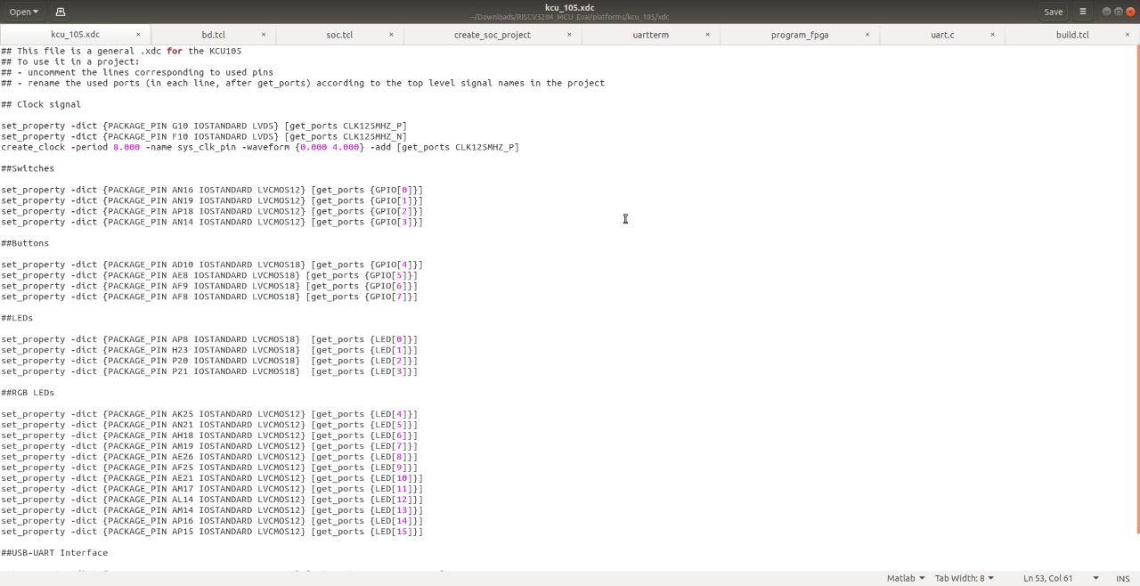
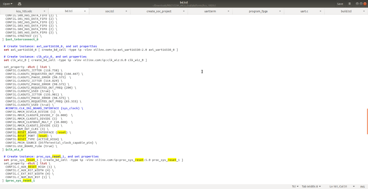
We are then able to use the Bluespec tool chain and the scripts provided by the RISCV32IM evaluation to recreate a new project. In this case, I used the following command:
MCU_INSTALL/utils/create_soc_project --project kcu105_port \
--core RISCV32IM_MCU \
--platform kcu_105
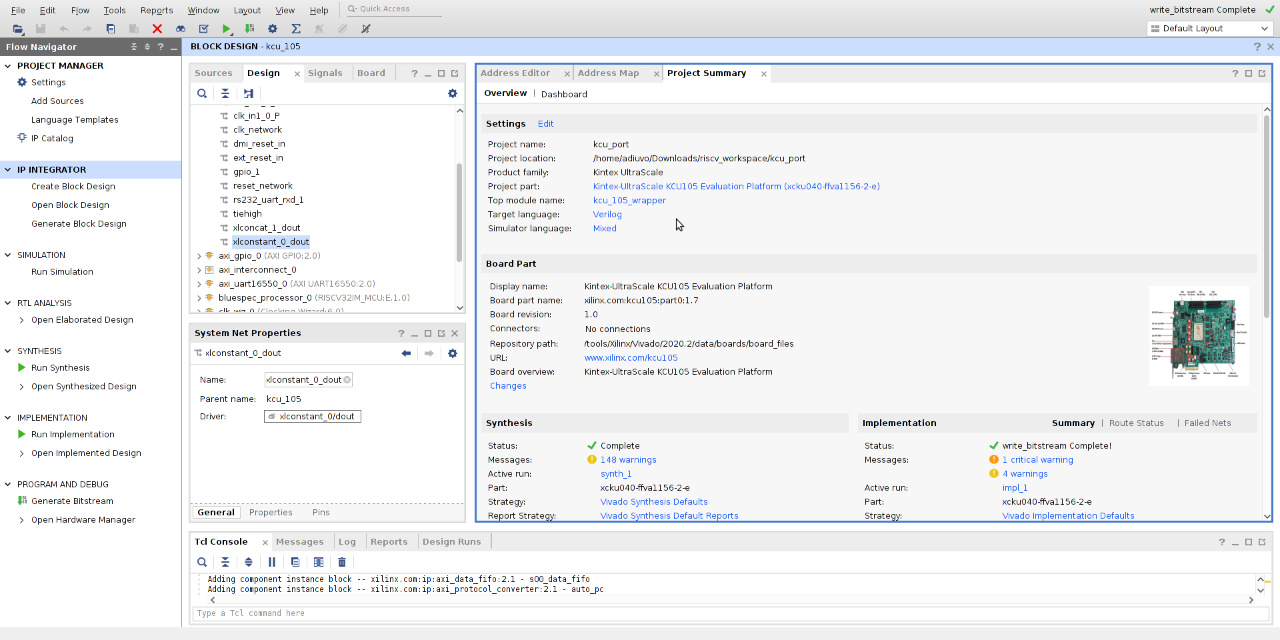
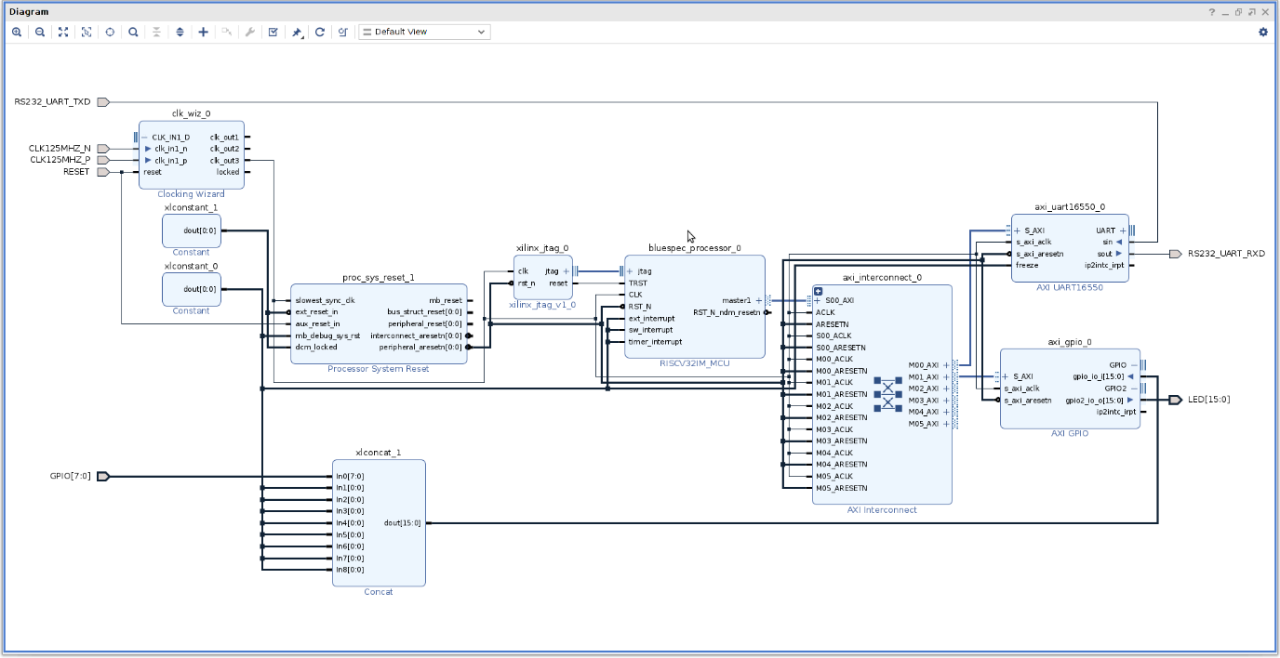
This created a Vivado project in my working area, which targeted the KCU105 board. Opening the project in Vivado shows the block diagram of the project in the KCU105 board.
Here, I am going to use the same application SW that was created for the first example. With the KCU105 project created, the next step is to build the bitstream and then download it to the KCU105 board.
We can do this using the commands:
$MCU_INSTALL/utils/build_bitstream --project kcu105_port \
--memhex $MCU_WORK/my_app/tcm.mem \
--jobs 2
$MCU_INSTALL/utils/program_fpga $MCU_WORK/my_project.bit
This will build and download the application to the KCU105 board. The board will then start executing the application, flashing the LED, and sending messages over the UART.
If you are using the utils/uartterm, this uses a script called detect_uart.pl and is currently configured to detect a Digilent USB device. This is not used on the KCU105 and may not be on your board either so you may need to change the script to pick up the serial interface you are using. You can find this under the /dev/serial/by-id. Once updated, the uartterm program should function just as before.
There you have it! A RISC-V processor and tool chain which makes it easy to port between Xilinx devices.
Xilinx Xclusive Blog
Adaptable Advantage 博客
-
- MicroZed Chronicles: Bluespec RISC-V
- Oct 01, 2021