AR# 68386
|Zynq UltraScale+ MPSoC ZCU102 Evaluation Kit - Board Debug Checklist
描述
The Zynq UltraScale+ MPSoC ZCU102 Evaluation Kit Debug Checklist is useful to debug board-related issues and to determine if applying for a Development Systems RMA is the next step.
Before working through the ZCU102 Board Debug Checklist, please review (Xilinx Answer 66752) - Zynq UltraScale+ MPSoC ZCU102 Evaluation Kit - Known Issues and Release Notes Master Answer Record, as the issue you are faced with might be covered there.
For more information on the ZCU102 that may not be covered here please see the ZCU102 Product Page and the Xilinx Wiki.
解决方案
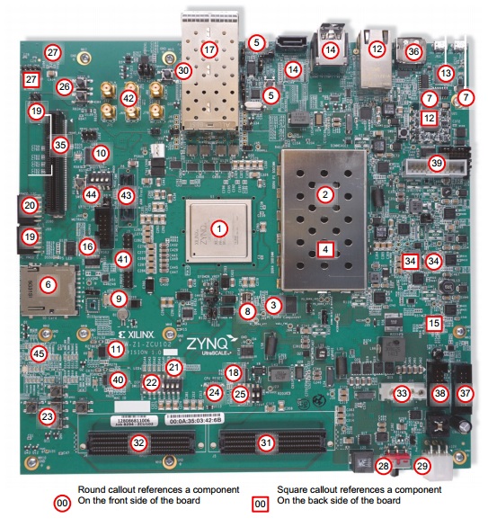
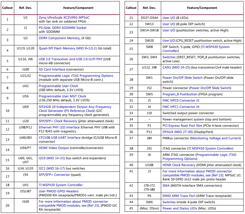
Figure 68386-1: ZCU102 Features Call-out
Table 68386-1: Callouts
The following debug steps assume steps 1-4 have been checked and are working:
1) Switch / Jumper Settings
Figure 68386-2 shows the board jumper header and DIP switch locations.

Figure 68386-2: DIP Switch and Board Header Jumper Locations
Default Switch and Jumper Settings for the ZCU102 are:
Start from a known safe scenario by verifying the default Switch and Jumper settings. You can then set switches / jumpers for your application.
a) DIP Switch Default Settings:
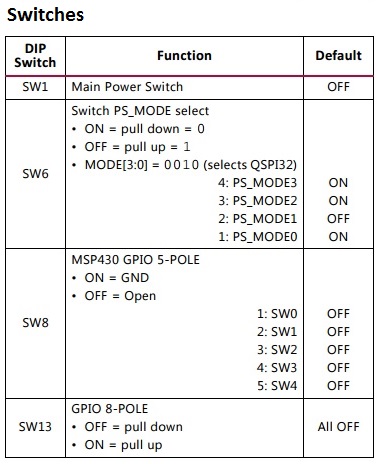
Table 68386-2: Default Switch Settings
b) Default Jumper Settings
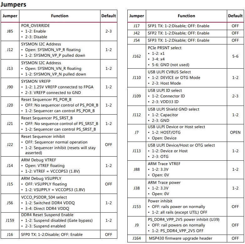
Table 68386-3: Default Jumper Settings
c) DIP Switch SW6 Configuration Option Settings:
Switch SW6 configuration option settings are identified in Table 68386-4.
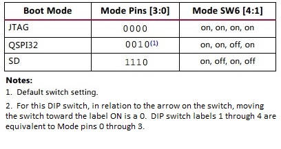
Table 68386-4: Switch SW6 Configuration Option Settings
2) Board Power
The ZCU102 hosts a Maxim PMBus based power system. Each individual Maxim MAX20751EKX, MAX15301, or MAX15303 voltage regulator has a PMBus interface.
Figure 68386-3 shows the ZCU102 power system block diagram.

The ZCU102 evaluation board uses power regulators and PMBus compliant POL controllers from Maxim Integrated Circuits to supply the core and auxiliary voltages listed in Table 68386-5 below.

The status of the Power-ON LEDs is an indication of board health.
a) Check the status of the following LEDs at Power-ON:

Table 68386-6: Power and Status LEDs
b) Check the status of these error LEDs at Power-ON. If they are lit then this indicates an error:

Table 68386-7: Error LEDs

Figure 68386-4: Location of Power and Status LEDs
This can be done using the Maxim Integrated PowerTool software package, and the Maxim Integrated USB cable.
Step-by-step instructions, together with the script to be used to reprogram the Maxim parts can be found in (Xilinx Answer 66811)
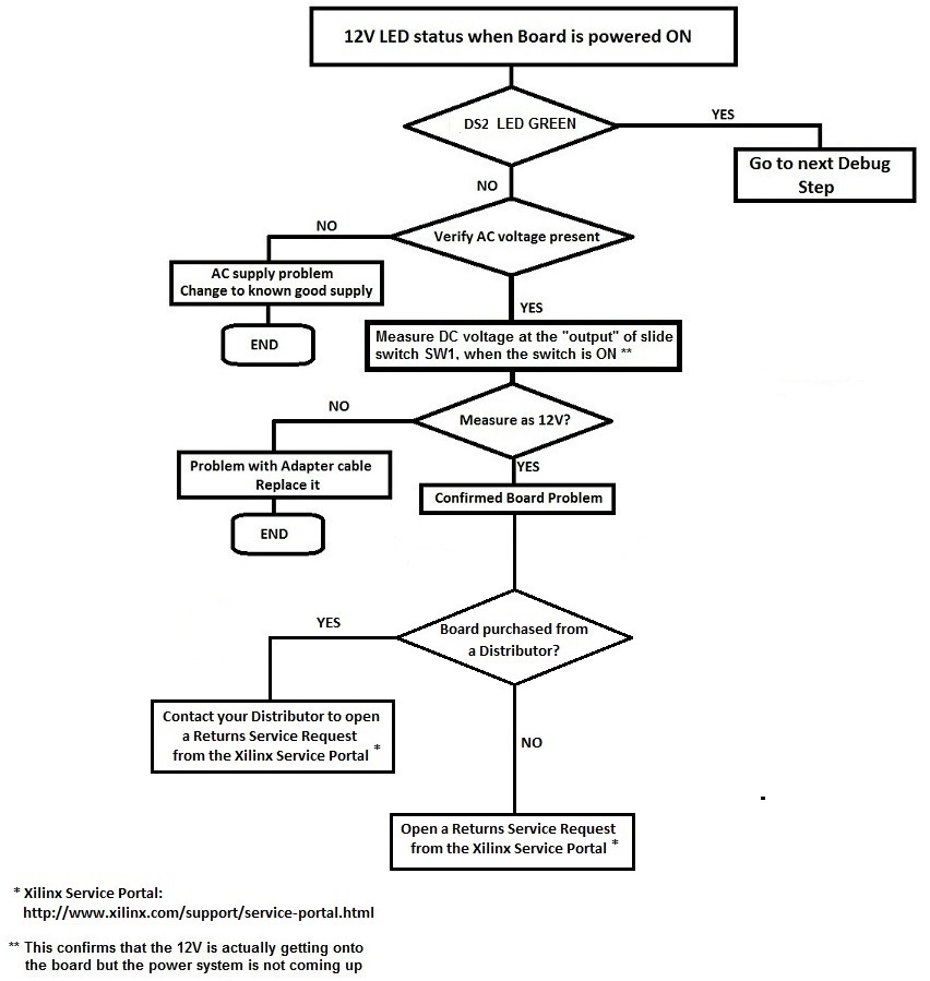
c) If the 12V Power LED (DS2 on the ZCU102) is not Green upon power up, then 12VDC is not being delivered to the ZCU102 power input connector.
Follow these steps:
The ZCU102 uses a USB A-to-micro-B cable plugged into the ZCU102 Digilent USB-to-JTAG module, U21.
A 2-mm JTAG header (J8) is also provided in parallel for access by Xilinx download cables such as the Platform Cable USB II.
a) USB A-to-micro-B cable:
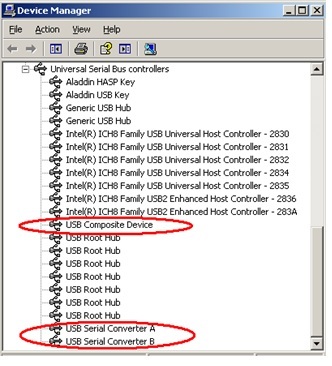
- Is the cable visible in Device Manager?
If the three items highlighted in the figure below are visible in Device Manager, this confirms that your USB cable is operational and has been correctly identified.
- Are cable drivers loaded correctly? Drivers for this cable should be included in the Vivado Design Tools installation.
However, if problems are experienced with USB A-to-micro-B cable connection, a Digilent plug-in can be downloaded from the link below.
For installation, please follow the guidelines in the document provided in the downloaded files:
http://digilentinc.com/Products/Detail.cfm?NavPath=2,66,768&Prod=DIGILENT-PLUGIN.
This plug-in requires Adept systems 2.4 or later for Windows and Adept systems 2.3.9 or later for Linux.
Adept software is available from Digilent:
http://digilentinc.com/Products/Detail.cfm?NavPath=2,66,828&Prod=ADEPT2.
- Check system properties and environment variables.
For information on environment variables, see (Xilinx Answer 11630). - Is the USB port enabled?
You can reboot your system to re-initialize the USB buses. - Are Xilinx tools correctly installed? (Vivado Hardware Manager or ILA)
For supported software version information, see the Kit Product Page:
https://www.xilinx.com/products/boards-and-kits/ek-u1-zcu102-es2-g.html
If an issue is suspected with tools installation, see the Installation and Licensing Guide (make sure to use the most recent version of tools and associated documentation which supports the KCU105).
https://www.xilinx.com/support/documentation/sw_manuals/xilinx2014_4/ug973-vivado-release-notes-install-license.pdf
- Is the Operating System (OS) being used Windows 7?
If so, please see (Xilinx Answer 41442) and (Xilinx Answer 44397).
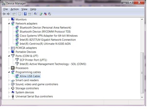
b) Platform Cable USB II
- Is the cable visible in Device Manager?
- Are cable drivers loaded correctly? Drivers for this cable should be included in the Vivado Design Tools installation.
However, if problems are experienced with the Platform Cable USB II connection, please follow the uninstall and reinstall instructions in (Xilinx Answer 44397).
- Check system properties and environment variables.
For information on environment variables, see (Xilinx Answer 11630). - Is the USB port enabled? You can reboot your system to re-initialize the USB buses.
- Are Xilinx tools correctly installed? (Hardware Manager or ILA)
For supported software version information, see the Kit Product Page:
http://www.xilinx.com/products/boards-and-kits/kcu105.html#overview
If an issue is suspected with tools installation, see the Installation and Licensing Guide (make sure to use the most recent version of tools and associated documentation which supports the KCU105).
http://www.xilinx.com/support/documentation/sw_manuals/xilinx2014_4/ug973-vivado-release-notes-install-license.pdf
- Is the Operating System (OS) being used Windows 7?
If so, please see (Xilinx Answer 41442) and (Xilinx Answer 44397).
If the above steps do not enable you to connect, please review the Support Webpage for your available Support options.
4) JTAG Initialization
The status of the board JTAG chain is checked using Xilinx Tools (Hardware Manager in Vivado).
To check to see that the JTAG chain is initialized correctly, follow this JTAG Initialization Test Case:
1. Remove any FMC cards from ZCU102.
2. Set the mode switch SW6 for JTAG mode (0000), which is ON ON ON ON for the ZCU102.
3. Power up the ZCU102 on the bench (not in a PC chassis).
4. Connect the Digilent USB A-to-micro B cable to the ZCU102 (through the Digilent onboard USB-to-JTAG configuration logic module - U21 - through header J2).
5. Check that the Digilent device shows up in the Device Manager.
6. Ensure Xilinx tools (Vivado 2016.4 or later - preferably the latest version of tools that support the ZCU102) are correctly installed.
7. Launch Vivado Hardware Manager - is the cable identified correctly?
- If not, see section 3) Cable detection above.
- If yes, but Vivado Hardware Manager did not discover and display the JTAG chain, slow down the cable speed (Output > Cable Setup).
- If yes, but Vivado Hardware Manager did not discover and display the JTAG chain and slowing the cable speed does not resolve the issue, see the following (assumes Digilent USB A-to-micro B cable is plugged into USB-to-JTAG configuration logic module U21 through J2):
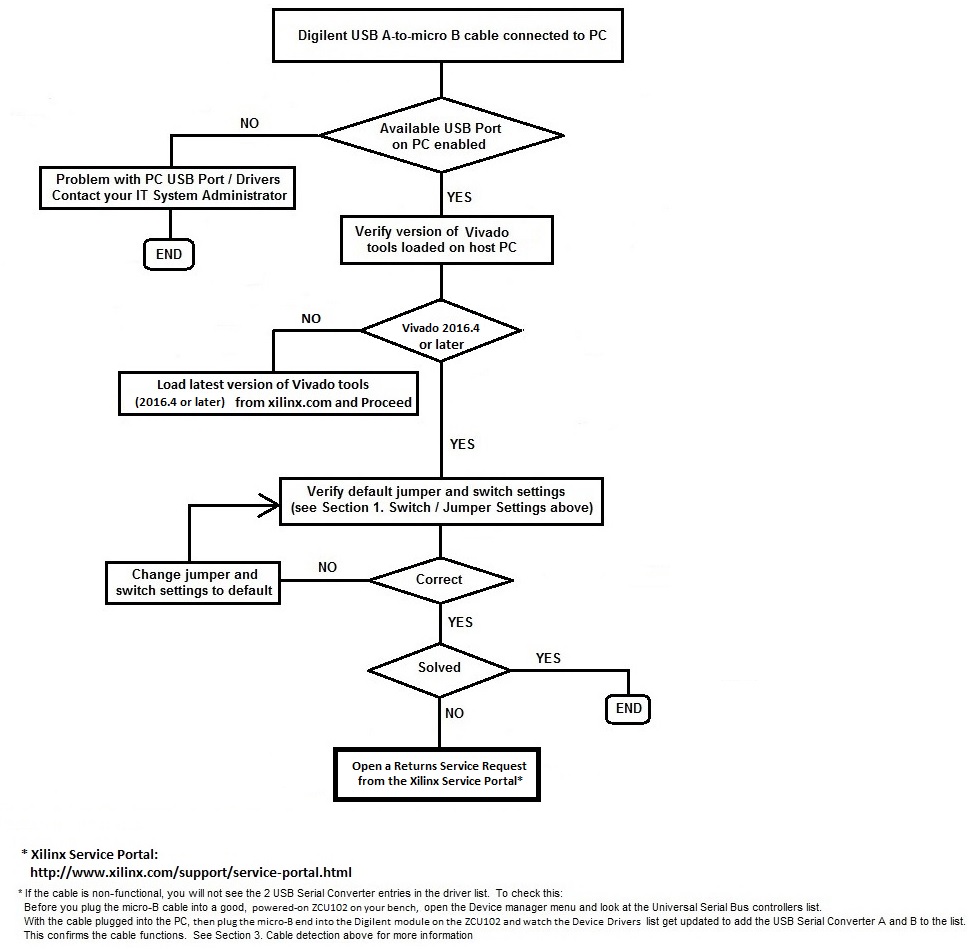
If following the above steps does not allow you to initialize the JTAG chain, please disconnect the Digilent USB A-to-micro-B cable from the board and PC.
Connect the Platform Cable USB to header J8, and connect to your PC.
Ensure Xilinx tools (preferably the latest version of tools that support the ZCU102) are correctly installed.
Launch Vivado Hardware Manager - is the cable identified correctly?
If following the above steps does not allow you to initialize the JTAG chain, please review the Support Webpage for your available Support options.
5) JTAG Configuration
If the JTAG chain initializes okay but JTAG configuration fails, check the following:
a) Verify the mode switch settings for JTAG configuration mode:
SW6 = 0000 (on, on, on, on)
b) In Vivado Hardware Manager, select a lower cable frequency and re-attempt configuration.
c) Pulse the PS_PROG_B push button on the ZCU102 (SW5). Pulsing PROG will clear out any problems caused by power up ramp rate issues to the FPGA.
d) Review (Xilinx Answer 34904) - Xilinx Configuration Solution Center. The Configuration Solution Center is available to address all questions related to Configuration.
If the above steps fail to enable JTAG configuration, please review the Support Webpage for your available Support options.
6) Quad-SPI configuration
Booting from the dual Quad-SPI non-volatile configuration memory is accomplished by storing a valid Zynq UltraScale+ MPSoC boot image into the Quad-SPI flash devices connected to the MIO Quad-SPI interface, setting the boot mode pins SW6 [4:1] = QSPI32, then either power-cycling or pressing the power-on reset (POR) pushbutton.
The Vivado Hardware Manager can be used to indirectly program the dual Quad-SPI flash device on the ZCU102.
A bitstream programmed into the dual Quad-SPI flash is used to configure the Zynq UltraScale+ FPGA U1. If you have loaded a .mcs file into the SPI flash on the ZCU102, and subsequent SPI configuration of the Zynq UltraScale+ MPSoC device fails, the following points should be checked:
a) If the .mcs file is correctly loaded, you will see the selected FLASH device added to the JTAG chain.
By clicking on the flash device, you will see the MCS file successfully loaded.
If you do not see the FLASH device attached to the ZU9EG device, see the Vivado Design Suite User Guide: (UG908) Programming and Debugging, or the latest version of the document available on Xilinx.com
b) Verify the mode switch settings for QSPI32 configuration:
QSPI32 Mode Pins[3:0] = 0010 (on, on, off, on)
c) In Vivado Hardware Manager, select a lower cable frequency and re-attempt configuration.
d) Pulse the PS_PROG_B (SW5) push button on the ZCU102, to attempt to reload the FPGA with the configuration image.
e) Review (Xilinx Answer 34904) - Xilinx Configuration Solution Center. The Configuration Solution Center is available to address all questions related to Configuration.
If the above steps fail to enable SPI configuration, please review the Support Webpage for your available Support options.
7) IBERT
If the ZCU102 configures correctly, but IBERT does not operate as expected, check the following:
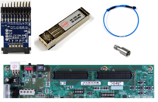
a) If using MGT loopback, ensure you have the correct equipment, including SMA cables, SMA Quick connects, Connect Optical Loopback Adapter, Mictor Breakout Adapter Plug, XM107.
Please see XTP435 ZCU102 Software Install and Board Setup for more information (some of this hardware is optional).
b) Download and run the ZCU102 IBERT Example Design, whichever version is appropriate for your silicon and software version.
It is recommended to always use the latest version of software which supports the ZCU102, and associated version of the ZCU102 IBERT Example Design.
Follow the associated PDF.
All are available from the ZCU102 Example Designs page.

c) Read the ZCU102 IBERT Example Design document: ZCU102 IBERT Tutorial: XTP430.pdf and follow the instructions therein.
d) IBERT Design Assistant: (Xilinx Answer 45562).
If the above steps fail to resolve the IBERT issue, please review the Support Webpage for your available Support options.
If a problem is suspected with DDR4 / MIG, check the following:
a) Ensure that the DDR4 SODIMM component memory is inserted correctly into socket J1
b) Download and run the ZCU102 MIG Example Design, whichever version is appropriate for your silicon and software version.
It is recommended to always use the latest version of software which supports the ZCU102, and associated version of the ZCU102 MIG Example Design.
Follow the associated PDF.
All are available from the ZCU102 Example Designs page.

c) Read the ZCU102 MIG Example Design document: ZCU102 MIG PDF: xtp432.pdf
d) Review (Xilinx Answer 34243) - Xilinx MIG Solution Center. The Memory Interface Generator (MIG) Solution Center is available to address all questions related to MIG.
If the above steps fail to resolve the DDR4 issue, please review the Support Webpage for your available Support options.
(Xilinx Answer 69244) can be run to ensure that the interfaces on the ZCU102 are working correctly.
This Answer Record forms part of (Xilinx Answer 43748) - Xilinx Boards and Kits Debug Assistant.
If the above tests fail to resolve the issue, please review the Support Webpage for your available Support options.
10) Known Issues for ZCU102
All Known Issues for the Zynq UltraScale+ MPSoC ZCU102 Evaluation Kit are listed in (Xilinx Answer 66752) - Zynq UltraScale+ MPSoC ZCU102 Evaluation Kit - Known Issues and Release Notes Master Answer Record.
If the issue you are faced with is not listed in the Known Issues and Release Notes Master Answer Record, and the steps above fail to resolve the issue, please review the Support Webpage for your available Support options.
链接问答记录
主要问答记录
| Answer Number | 问答标题 | 问题版本 | 已解决问题的版本 |
|---|---|---|---|
| 43748 | Xilinx Boards and Kits - Debug Assistant | N/A | N/A |
| AR# 68386 | |
|---|---|
| 日期 | 06/30/2017 |
| 状态 | Active |
| Type | 综合文章 |
| Boards & Kits | |