MicroZed Chronicles: PYNQ Interrupts
July 22, 2022
Editor’s Note: This content is republished from the MicroZed Chronicles, with permission from the author.
Last week, after we looked at how we could use the AXI IIC IP with PYNQ, I got a question from a reader asking how we work with interrupts in PYNQ. The answer is that much of the complex interrupt handling like VDMA is handled automatically.
However, there are situations that need to be handled by the application running on the PS such as fabric interrupts from custom IP in the programmable logic.
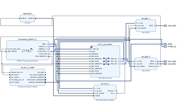
To demonstrate how interrupts from the PL to the PS can be addressed in PYNQ, I put together a simple hardware project which connects the push button switches and the four LEDs to the processor system using AXI GPIO. For this project, I again targeted the PYNQ-Z1 and added in the AXI GPIO modules. I ensured that the interrupt option was enabled on the AXI GPIO which was connected to the push button and switch inputs.
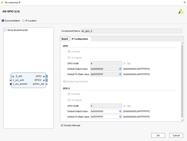
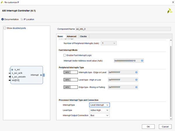
This interrupt was connected to a AXI interrupt controller which has been configured to raise a level interrupt not an edge when triggered.
The final bit stream image capture can be seen below.
Once the bitstream was generated, I transferred the Hardware Handoff File and bit stream to a new folder on the PYNQ board.
The first thing I did in the PYNQ environment was to create a new notebook and download the overlay just created.
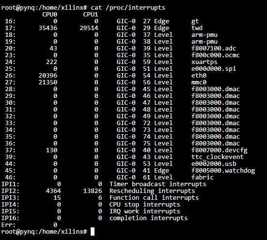
Once this was completed using a terminal window, I checked the interrupts present in the command cat proc/interrupts. This showed a level triggered fabric interrupt.
Now we can start creating the application and use the push button switches to generate the interrupt. When the interrupt occurs, we will toggle the LED status.
To make use of the interrupt, we use the asyncio features of Python. Asyncio enables us to work with several peripherals without blocking execution of the overall application. At its heart, asyncio uses four structures:
- Coroutines – These are functions that can halt execution at a given point in time until a task or event occurs. Two new keywords were introduced to do this: async is typically used to define the coroutine; and await is the point at which the program pauses execution.
- Futures – Futures encapsulate pending operations so they can be put in queues. Their state of completion can be queried and their results can be retrieved when ready.
- Task – Tasks contain coroutines which are registered with an asyncio event loop.
- Event loop – The event loop executes all of the ready tasks by polling suspended tasks and scheduling outstanding tasks.
To get started creating an interrupt-based system, we need to import the asyncio library, create a coroutine for the interrupt handler, define the future for the coroutine, and create the event loop.
If we want to see what interrupts are enabled in a current overlay, we would use the following command:
<overlayname>.interrupt_pins
In this instance, it shows an interrupt from the GPIO as connected to the interrupt controller.

If we are working with a custom IP block in the PL which drives a fabric interrupt, we can then access the interrupt pin using the following command:
intr_inst = Interrupt('axi_gpio_0/ip2intc_irpt')
We do not need to do this when we use the GPIO because the AXI GPIO already has a coroutine available for interrupts.
We then need to define our own coroutine which waits for the actions on the buttons and then toggles the LEDS. We do this using the ASYNC keyword.
async def handle():
await sw.wait_for_interrupt_async()
#await intr_inst.wait()
leds[0:3].toggle()
The next step is to create the handler for the task using the following future:
handler_task = asyncio.ensure_future(handle())
Finally, we can run the event loop. In this case, it will run until the handler task completes but we could make it run continually if we wanted to.
asyncio.get_event_loop().run_until_complete(handler_task)
As we run this, we should see the LEDS toggle on the PYNQ-Z1 board. We should also be able to see the number of interrupt events occurring if we observe the processor interrupts again.
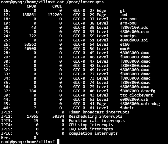
In the above image, notice that the interrupt has occurred seven times while I tested the code for this blog.
The complete notebook can be seen below.
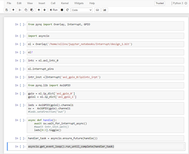
Now we know how we can work with interrupts in the PYNQ environment.
Xilinx Xclusive Blog
-
- AMD-赛灵思公布 2021 自适应计算挑战赛开发者赛道获胜者
- Apr 28, 2022
-
- 启动您的引擎:Versal Premium 系列引入 AI 引擎,“加速”信号处理
- Apr 20, 2022
-
- 基于自适应计算的尖端音视频与广播方案亮相 ISE 2022
- Apr 06, 2022
Adaptable Advantage 博客
-
- MicroZed Chronicles: PYNQ Interrupts
- Jul 22, 2022
-
- Configurable Low Latency Streaming
- Jul 21, 2022
-
- MicroZed Chronicles: PYNQ and AXI IIC
- Jul 15, 2022