MicroZed Chronicles: PYNQ and AXI IIC
July 15, 2022
Editor’s Note: This content is republished from the MicroZed Chronicles, with permission from the author.
One of the most widely used embedded protocols for low-speed communication between embedded devices is the I2C. We have a choice about how to use the I2C with the Zynq, MPSoC and Versal devices. Here are some options:
- Drive the I2C interface from the PS I2C controller and use allocated MIO pins
- Drive the I2C interface from the PS I2C controller and use EMIO pins in the PL
- Implement a AXI IIC IP block within the PL and connect the pins to the PL IO
We’ve used the PS I2C controllers in many of our PYNQ projects to configure HDMI interfaces and read sensors etc. When doing so, we have the ability to use helpful I2C tool packages and scan buses and networks etc. because they are included in the device tree.
We take a slightly different approach when adding the AXI IIC IP block into the PL by using the PYNQ AXI IIC library. It is this approach that we are going to look at today using the PYNQ-Z1.
To get started in Vivado, we first create a new project targeting the PYNQ-Z1 board.
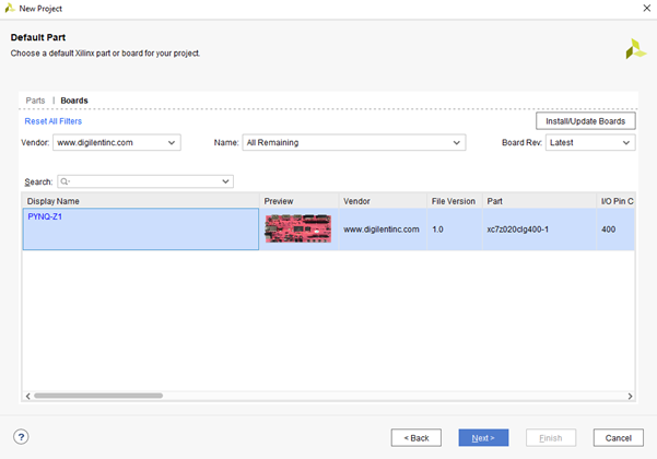
The next step is to add in the following IP blocks:
- Zynq-7000 processing system – Run the board automation to configure it for the PYNQ-Z1
- AXI IIC IP block – leave settings unchanged
- AXI interrupt controller – leave settings unchanged
Run the connection automation to create the AXI and reset network. Next, connect the interrupt from the AXI IIC IP block to the AXI interrupt controller and from the AXI interrupt controller to the PS fabric interrupt.
The finished block diagram should look like the image below.
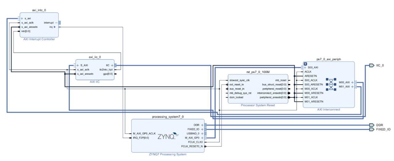
With the design completed, the next step is to assign the IO pins in the XDC file. Remember to add pull up resistors for I2C if the board does not have them. I targeted a PYNQ-Z1 for this project and used Pmod B so my XDC file looks as below
set_property PACKAGE_PIN T11 [get_ports IIC_0_scl_io]
set_property PACKAGE_PIN T10 [get_ports IIC_0_sda_io]
set_property IOSTANDARD LVCMOS33 [get_ports IIC_0_scl_io]
set_property IOSTANDARD LVCMOS33 [get_ports IIC_0_sda_io]
set_property PULLUP true [get_ports IIC_0_scl_io]
set_property PULLUP true [get_ports IIC_0_sda_io]
Once the bit stream is built, we can connect to the PYNQ-Z1 using a Samba network share from our development machine and upload the bit file and hardware handoff file.
We can then get started building the Jupyter Notebook which is straight forward for this application. I also attached scope probes to the SDA and SCL lines on the Pmod B.
To work with the AXI IIC, we are going to be using the AXI IIC library included within PYNQ.LIB.IIC. This provides the ability to bind to a AXI IIC IP within the hardware and read and write over the I2C bus.
Many I2C devices require a write first to set the register value to be read from the slave and the functions also give us the ability to do a repeated start to keep the bus.
To bind the AXI IIC IP to an object, we can use the AXI IIC function and look up the specific AXI IIC IP we wish to bind to in the hardware overlay. There is only one AXI IIC in the design which we can bind to in this application. I used the dictionary to select it.
We can then send and receive I2C data using the send and receive functions. Both are pretty simple and have the following formats:
Send (Address, Data_array, Length of Data Array to send, Repeated_start)
Receive (Address, Data_array, Length of Data Array to RX, Repeated_start)
Repeated start is either 1 to perform a repeated start at the end of the transaction or 0 to perform a I2C stop.
To test this approach out, I connected a Digilent Pmod HYGRO to the PYNQ-Z1 and attempted to read its device ID register.
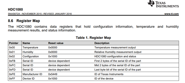
This register lives at 0xFF and should respond with the Hex value 0x1050. The Jupyter Notebook to do this is below.
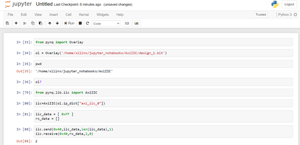
Running the code on the PYNQ-Z1 board and reading the required values back from the Pmod HYGRO showed the I2C bus to be working as intended.
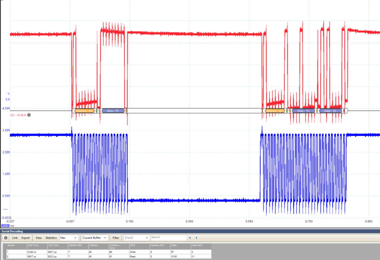
If you see a warning indicating the I2C data is unable to send, check the I2C address because it’s likely there wasn’t an ACK from the device that you are trying to communicate with.
This library is very useful for working with I2C when we have AXI IIC IP in the PL and we want to work with PYNQ.
Xilinx Xclusive Blog
-
- AMD-赛灵思公布 2021 自适应计算挑战赛开发者赛道获胜者
- Apr 28, 2022
-
- 启动您的引擎:Versal Premium 系列引入 AI 引擎,“加速”信号处理
- Apr 20, 2022
-
- 基于自适应计算的尖端音视频与广播方案亮相 ISE 2022
- Apr 06, 2022
Adaptable Advantage 博客
-
- MicroZed Chronicles: PYNQ Interrupts
- Jul 22, 2022
-
- Configurable Low Latency Streaming
- Jul 21, 2022
-
- MicroZed Chronicles: PYNQ and AXI IIC
- Jul 15, 2022