MicroZed Chronicles: Scripting Vivado ML
January 28, 2022
Editor’s Note: This content is republished from the MicroZed Chronicles, with permission from the author.
Throughout the nine years I’ve been doing this blog, the majority, if not all, of the examples and Hackster projects have been implemented using the GUI. It makes sense to provide visual representation of the concepts I am trying to explain, however, I tend to use scripting for many of my professional developments. This ensures repeatability and provides a nice, simple file set which can be stored in configuration management tools like Git.

First, we need to understand which of the two project flows we wish to use: project mode or non-project mode. Both can be implemented using Vivado GUI or command-line approaches. Project mode is the most used in GUI mode, whereas scripting is most used in non-project mode. Let’s take a look at the differences.
Project Mode – Vivado creates a directory structure on disk to manage design source files, manage changes, and modifications. This means that if we change a file, either RTL or constraints Vivado automatically prompts to re-run the stages required. At the end of routing, Vivado also automatically generates timing, DRC, methodology, and power reports.
Non-Project Mode – In this mode, the developer is responsible for the management of all sources and the design process. If files are modified, the developer must remember to re-run the appropriate stages. Compilation is stored in memory and the developer must save reports and design checkpoints if required. TCL commands are used to set tool implementation options.
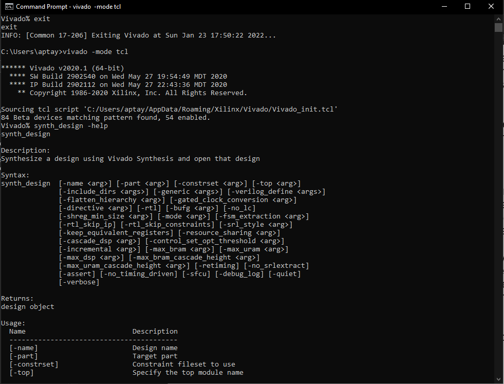
To get started with scripting, we have two approaches that we can take. The first is to start Vivado in the TCL mode. This will open the TCL command window and allow it to execute TCL commands or scripts. This is very useful for developing the scripts and understanding the commands and options for each command.

While batch mode is meant to be used once the script is developed and will open Vivado, run the scripts and exit Vivado once the script has been completed.
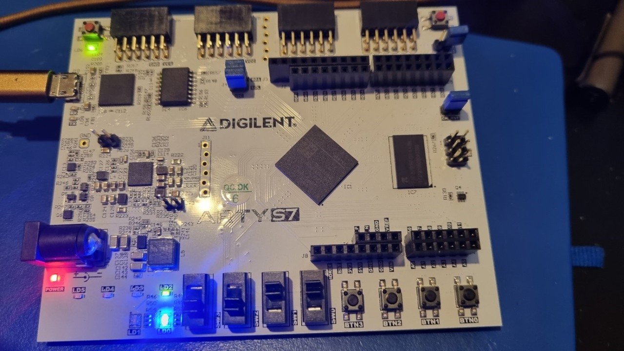
Let’s look at a simple project in both project and non-project scripting flow. We will use the same RTL and XDC file for both examples. It is a simple file which drives the tri-color LED on the Arty S7-50 board from the switches.
The script for the project flow can be seen below.
set outputDir ./projectflow
file mkdir $outputDir
create_project project_flow_mz428 ./$outputDir -part xc7s50csga324-1 -force
add_files ../led_fsm.vhd
add_files -fileset constrs_1 ../io.xdc
import_files -force -norecurse
set_property top top [current_fileset]
update_compile_order -fileset sources_1
launch_runs synth_1
wait_on_run synth_1
launch_runs impl_1 -to_step write_bitstream
wait_on_run impl_1
puts "Implementation done!"
set_param labtools.override_cs_server_version_check 1
open_hw_manager
connect_hw_server -allow_non_jtag
open_hw_target
set_property PROGRAM.FILE {C:/hdl_projects/scripting/project/outputDir/project_flow_mz428.runs/impl_1/led_fsm.bit} [get_hw_devices xc7s50_0]
current_hw_device [get_hw_devices xc7s50_0]
refresh_hw_device -update_hw_probes false [lindex [get_hw_devices xc7s50_0] 0]
program_hw_devices [get_hw_devices xc7s50_0]
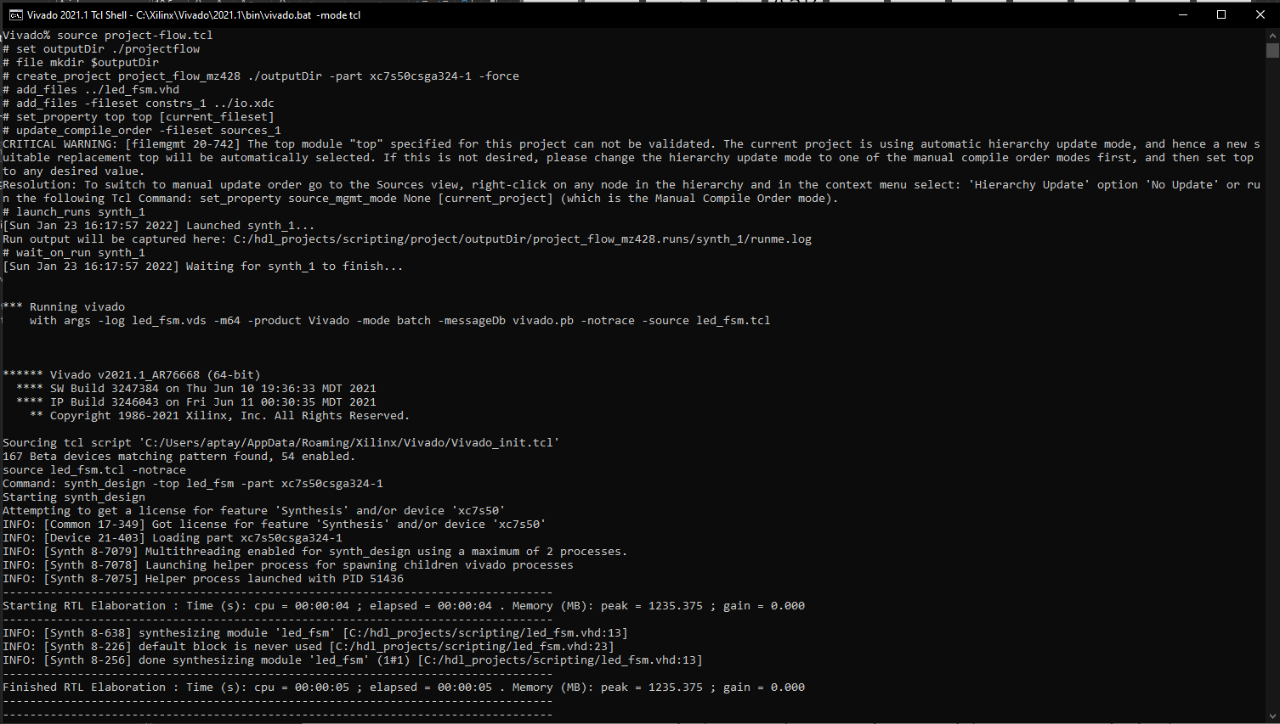
This script creates a Vivado project targeting the Spartan-7 and adds an RTL and constraints file to the project before launching synthesis. Once synthesis is completed, it launches the runs and creates the bitstream.
Finally, once the bitstream is ready, it connects to the HW manager and downloads the application to the target board, provided that the target board is connected. Of course, in reality, you might want to implement flow control in the script or command line options to run different elements (e.g., not programming the HW unless desired).

The non-script flow script can be seen below.
set outputDir ./nonprojectflow
file mkdir $outputDir
read_vhdl ../led_fsm.vhd
read_xdc ../io.xdc
synth_design -top led_fsm -part xc7s50csga324-1
write_checkpoint -force $outputDir/post_synth.dcp
report_utilization -file $outputDir/post_synth_util.rpt
opt_design
place_design
write_checkpoint -force $outputDir/post_place.dcp
route_design
write_checkpoint -force $outputDir/post_route.dcp
write_bitstream -force $outputDir/led.bit
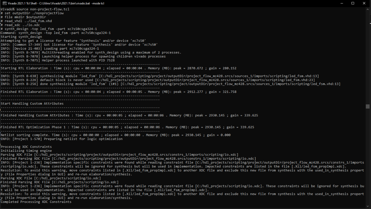
Since we don’t have a project, we need to inform the synthesis engine of the top-level entity/module name and the target part in the RTL and XDC scripts before synthesizing the design. Once that is completed, as in-memory flow is used. For non-project modes, I write out the synthesis checkpoint and the utilization report. Once the synthesis is completed, the next step is to run the optimization and place. I write out the DCP again at the end of the place. The final stage is to run the routing and save its DCP before generating the bitstream.

Looking at both the project and non-project flow, there are several immediate differences. The first, of course, being the difference in TCL commands used.
Both approaches have their pros and cons. The project flow ensures you do not forget any stages while the non-project flow provides the ability to work easier with different directory structures and configuration management.
The scripts etc. are all uploaded to my GitHub.
Xilinx Xclusive Blog
-
- 准备呐喊助威吧:赛灵思将参加 BattleBots电视系列角逐赛
- Dec 07, 2021
-
- 50 多家领先的公司、大学和研究机构将在 Xilinx Adapt 2021 上发言
- Sep 01, 2021
-
- 嵌入式 AI 需要什么样的解决方案
- Sep 01, 2021
Adaptable Advantage 博客
Xilinx AI 和软件博客
-
- Vitis AI 2.0 现已推出!
- Jan 20, 2022
-
- 连获“双奖”,Xilinx AI 团队实力绽放国际视觉顶会
- Oct 08, 2021
-
- 您是否了解过赛灵思应用商店?评估和购买 Alveo 及 Kria SOM 解决方案的一站式商店。
- Sep 23, 2021