MicroZed Chronicles: Signal Processing, FFT, and PYNQ
June 17, 2022
Editor’s Note: This content is republished from the MicroZed Chronicles, with permission from the author.
One of the great things about FPGAs is the parallel structures and how we can accelerate the algorithms by exploiting the parallel nature of programmable logic. A few weeks ago, we looked at the AXI Stream FIFO and how it could be used to communicate with AXI streaming devices.
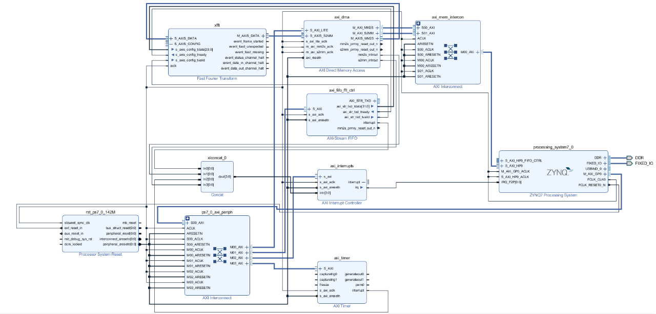
In this blog, I am going to show how we can use an AXI Stream FIFO, DMA, and PYNQ to demonstrate the acceleration that is possible when implementing a FFT in the programmable logic compared to doing it in software on an A9 processor.
This is quite complex so I have created a step-by-step guide which is available here. We are going to do the following elements to create this application:
- Add a Zynq PS block and configure it for the PYNQ Z1/ Z2
- Instantiate a FFT in the programmable logic
- Instantiate a DMA in the programmable logic
- Connect the stream Master and Slave interfaces of the FFT to the DMA. This enables up to insert samples and receive processed data.
- Instantiate an AXI Stream FIFO and connect it to the FFT Stream Config Input
- Instantiate an AXI Timer and connect to the AXI GP Bus
- Instantiate an AXI Interrupt Controller and connect to the fabric-to-processor interrupt on the Zynq PS block
This is what the finished block diagram looks like.

We are able to build the bitstream with the hardware implemented. While the FPGA image builds, we can burn a PYNQ image to the SD card and start creating the Jupyter Notebook.
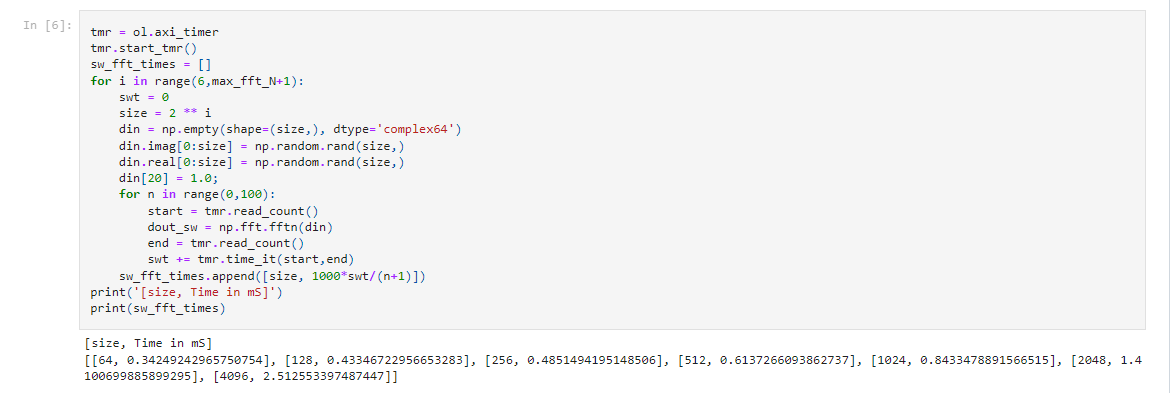
The PYNQ Notebook is going to download the overlay to the PYNQ-Z1. It will then create real and imaginary sample data before of different sample lengths. This data will then be used to calculate the FFT in software using NumPy.

Since the AXI Stream FIFO is used to control the FFT, the notebook also creates several functions that can be used to send data to and from the AXI Stream FIFO correctly.
There are two FFT drivers provided with the overlay. The first driver does a copy to and from the DMA and handles buffer allocation etc. The second method requires pre-sizing and buffering and reduces the time required for copying and buffer allocation / freeing associated with the first.
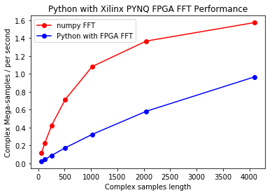
The notebook then uses the first method to run through seven different FFT sizes and runs 100 times to calculate the difference in performance between HW implementation and SW implementation. This information is then plotted and is seen below. As can be seen with the inefficient transfer of data, the A9 processor cores can perform much better than the FFT in the IP core.

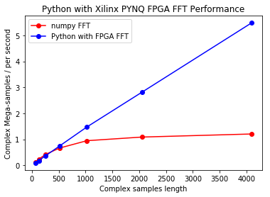
However, the next stage of the notebook is to use the more efficient transfer which resizes the buffers correctly first. When the notebook is run in this instance, it is clear the FFT IP in the PL significantly outperforms the SW FFT as would be expected.

This simple experiment shows several things:
- The major performance improvement is efficient data transfer between PS and PL. The correct efficient drivers for this are critical.
- PYNQ enables rapid prototyping to ensure your algorithms and drivers provide the performance required /expected.
- PYNQ enables visualization of the results and also enables real-world data to be inserted very easily into the processing chain.
- We can use it as a pointer for SW application development in PetaLinux as required.
If you want to have a try at the Arty Z7-20 or PYNQ-Z1, follow along through the slides to rebuild and download the bit file from here. Happy experimenting!
Xilinx Xclusive Blog
-
- AMD-赛灵思公布 2021 自适应计算挑战赛开发者赛道获胜者
- Apr 28, 2022
-
- 启动您的引擎:Versal Premium 系列引入 AI 引擎,“加速”信号处理
- Apr 20, 2022
-
- 基于自适应计算的尖端音视频与广播方案亮相 ISE 2022
- Apr 06, 2022
Adaptable Advantage 博客
-
- MicroZed Chronicles: PYNQ Interrupts
- Jul 22, 2022
-
- Configurable Low Latency Streaming
- Jul 21, 2022
-
- MicroZed Chronicles: PYNQ and AXI IIC
- Jul 15, 2022